by Francois Carrez, PhD, University of Surrey

Introduction
The purpose of this architecture post is to introduce the reader to the system architecture of the DEDICAT 6G project. To start with, DEDICAT 6G does not provide a 6G architecture per se; its approach consists of augmenting an existing 5G network (Core and RAN) with a set of novel capabilities that are referred to as the three main project (technical) pillars, namely, dynamic intelligence distribution, radio coverage extension and end-to-end Security, Privacy and Trust. In this series of posts, we will consider mostly the two first pillars.
Part 1 – Basic Principles
Before going into greater detail in the following posts, we will focus here at first, on providing some basic principles followed by the DEDICAT 6G platform, then on giving a short description of the components involved and finally on illustrating the architecture and introduced functional components with a simplified architecture figure which shows the platform and its main constituents, alongside the few 5G components of the 5G Core the platform is interacting with in order to support some of its features.
Main concepts of the platform
In the following text that elucidates the SenseAwarenessDecideAct loop implemented within the architecture, we will refer to the Data-Information-Knowledge-Wisdom (DIKW) pyramid model1 which is sometimes used to show how initial raw data can be enriched/enhanced before ultimately reaching the latest step where decisions are undertaken (Wisdom).
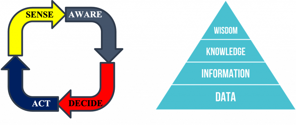
Figure 1: Cognitive loop (left) and DIKW pyramid (right)
The general way the platform is operating complies with the cognitive loop (shown above) where:
- “Sensing”: is undertaken mostly by DEDICAT 6G agents scattered at the Edge/Far Edge (e.g., within 5G Mobile Access Points (MAP) and (far) Edge (computing) Nodes (EN)), but also -at the 5G System side- by components such as Network Exposure Function (NEF) and NetWork Data Analytics Function (NWDAF). Sensing aims at collecting raw Data (the D in DIKW), adding also some useful meta-data reaching the Information level of the DIKW model; that information is then forwarded to the next layer for enrichment;
- “Awareness”: is about the collection, aggregation and analysis of information received from the myriad of agents introduced above. They aim to build contexts for the decision-making components to use; here we reach the Knowledge level of the DIKW model. It is worth noting also that different sorts of agents and aggregators are used depending on the nature of the initial raw data. Consequently, we will be dealing with Network (NW), Mobile Access Point (MAP), User Equipment (UE), Edge Node, micro-services (µS)/FC-related contexts which are in turn used by the various DM components depending on their roles and inner goals. Designing this layer and structuring contexts are paramount as they are expected to characterize the environment as a whole without discarding essential information to be used in the next steps of the loop below;
- “Analysing & Deciding”: this role is undertaken by the decision-making components. Based on contexts that give an overall (but still precise with good granularity level) “picture” of the whole system being monitored (in that precise case, the DEDICAT 6G platform including the edges and the supporting legacy 5G network) the service logics embedded in the Decision-Making (DM) components take decision according to their inner objectives, reaching then the Wisdom level of the DIKW model. Such objectives are e.g., maintaining appropriate Quality of Service (QoS), palliating equipment failure, answering an optimization recommendation, providing a service to a vertical etc. What will make the difference between a proactive or reactive DM, depends on how the DM logic is built: if this logic is driven by recurring goals and issues actions (intents) based on internal beliefs embodied into contexts, the behaviour of the DM can be seen as “pro-active”. If its service logic is driven by incoming events and implemented as a rather static set of rules, it would be considered “reactive”. Of course, adopting a hybrid architecture approach -like we do in DEDICAT 6G- is also feasible and sound;
- “Acting”: this final step of the loop implements the decisions undertaken by the DMs and is taken care of by several components that are either hosted in the cloud or deployed towards the Edge/Far Edge.
After this short introduction of the cognitive loop, we give some more detail about the components that endorse the four roles described above. Figure 2 below, gives a glance at the platform components , the information they exchange, and how they interact with each other.
Going back to the SenseAwarenessDecideAct loop we can see (in blue), the Awareness Functional Components (FC) responsible (see Awareness role) to aggregate the 5 different sorts of context from the information pushed by their respective agents (not shown in the figure and undertaking the Sensing role). We can notice straightaway the flow of information flowing from those awareness FCs towards the decision-making components (in green). Based on such contexts, the DM components (they are the components of the Decide role) are taking decisions. That’s eventually what they are meant to do! But each of them with focus on different matters in order to avoid interference-like issues. We call that “separation of duties”. Consequently:
- The Network Operation Decision Making (NODM) component is focused on monitoring the 5G network operation and other networking aspects relating to Edge Nodes operation. It detects equipment failures (as reported by NEF/NWDAF) or receives network optimization recommendations from the NW Optimization component (in yellow). The NODM is also responsible for network slicing, but this topic is for another blog post. Whenever the NODM considers that a network problem must be corrected using coverage extension, it triggers the Coverage Extension Decision Making accordingly, providing it with the necessary information;
- The Coverage Extension Decision Making (CEDM) component is managing a CE request, decides about its dimensioning and characteristics (e.g., location of MAP deployment) and decides about the nature and number of MAPs that need to be deployed in order to extend the coverage of the existing Radio Access Network at the determined location; The CEDM relies on the Intelligence Distribution Decision Making component for all decisions that concern the deployment and placement of DEDICAT 6G components (typically agents, but also other DEDICAT 6G components that need being deployed at the far edge);
- The Intelligence Distribution Decision Making (IDDM) will decide about the taskedge Node/MAP allocation, where task collectively refers to 5G network functions, functional components or any other service (such as the µServices which we will introduce in a following post). This placement is an optimization problem that takes into account a lot of parameters and requirements relating to the FCs, services and Network Functions (NF) execution such as needed CPU/GPU, memory, bandwidth, latency, etc… but also additional ones such as energy consumption.
So far, we have introduced the Sense, Awareness and Decide components. The last role, namely Act, is covered by several additional components (in light purple) which are responsible for implementing the decisions issued by the NODM, CEDM and IDDM.
- Service Orchestrator is responsible for deployment of the different tasks and their operation. Another aspect of its duties relates to network slicing. The service Orchestrator relies on the Edge Orchestrator and Load Balancing FCs (in purple at the left of the figure). In a nutshell those FCs are responsible for the placement of the different tasks within their allocated edge nodes (by the IDDM). The service orchestrator may decide to reshuffle them among the available Execution Environment (EE) within an edge node/MAP, should their execution be not optimal or degraded. If another placement becomes necessary, the IDDM would issue another placement decision;
- MAP Operation FC: this component is the main entry point to CE operation. It is responsible for implementing the CEDM decision which includes 1/ the MAP configuration, as far as deploying Network Functions is concerned, 2/ some aspects of the network slice(s) life cycle, 3/ the management of the CE service life-cycle, and 4/ the the management of the operation of the various MAPs. Those aspects will be elucidated further in a next post;
- Service Orchestrator, Network Function Virtualization – Orchestrator (NFV-O) Connector and Software Defined Network – Controller (SDN-C) Connector are supporting the NODM as far as network slicing decisions are concerned.
Finally, it is worth noting, that additional components such as repositories and registries (in orange) provide necessary information to support the decision-making FCs, such as deployment policies, execution requirements of tasks in general.
Part 2 – The context awareness framework
Example of component deployment
To start with, let’s consider the simplified DEDICAT 6G architecture in the Figure 2 below.
In part 1 (above), we have briefly introduced Edge Orchestrator and Load Balancing components but did not tell much about how and where they are actually deployed.
Also, we introduced the MAP Operation component which is responsible for implementing the coverage extension decisions without telling much about how it interacts with the MAPs.
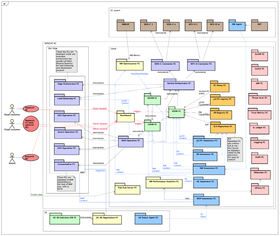
Figure 2: Decision Making and its interactions
In DEDICAT 6G – and especially in the 4 Use Cases we used for the purpose of demonstrating our results – several kinds of MAPs were considered:
- UAVs such as drones: our drones are 5G drones. As an individual drone, it can navigate to a 3D coordinate and act there as a 5G access point;
- Swarm of drones: several drones (their types and number are determined by the CEDM) are deployed at a location and will self-organize spatially according to the UE positions, by interacting with each other based on information coming from other drones, the Network Performance Analytics and MAP Awareness components;
- AGVs such as Robots: they can be used for different purposes such as loading and moving parcels or crawling under collapsed buildings in order to provide rescuers with video feeds;
- (so-called) Connected Cars: they are man-driven and can carry small servers/PCs and one mobile gNB. In some cases, they can also carry a micro 5G Core so that the connected car can be eventually used to build up an autonomous and standalone 5G network, also called “Tactical Bubble”. This scenario is typically explored in Case 1 of UC3 “Public Safety” that related to Disaster Relief.
It is worth mentioning two important aspects. First all MAPs are also Edge Nodes (EN). This means that they are potential targets of the IDDM when it performs task EN allocation. Second, all MAPs are IAB-enabled, where IAB stands for Integrated Access and Backhauling. IAB was introduced in 3GPP Release 15 and allows MAP to provide on one side access (to UEs) and on the other side a backhaul link towards a standard gNB.
But there is something more. An IAB-node can provide access, not only to UEs but to another IAB-node, and the backhaul link can address also another IAB-node. This means that using multiple IAB-nodes enables multi-hop communication from a standard gNB towards UEs. This becomes particularly handy when trying to densify communication in complex terrain, and as such offers lot of flexibility.
In DEDICAT 6G architecture, the whole coverage extension concept relies on using IAB technology.
As far as MAPs are concerned, they are all assigned some specialized FCs tailored to their nature and capabilities:
- UAVs: UAV Operation FC and Swarm Operation FC are dealing respectively with basic and advanced features of drones. Basic features are about navigation and collision avoidance (which is an autonomous function of the drone). Advanced features are the self-organizing capability of a swarm of drones where each drone position itself w.r.t. the rest of the swarm in an optimized way, to maximize association with UEs. The whole process is collaborative and based on multi-agent systems;
- AGVs: AGV Operation FC is the component dealing with the (unique) sort of robot we used in DEDICAT 6G. Since, each sort of robots displays different skills, as many <XXX> Operation FCs are usually needed if dealing with heterogeneous robots;
- Connected Car: Connected Car FC deals with non-human driven related tasks;
The interface provided by those components includes -besides aspects relating to normal operation- configuration functions (including radio-related) and additional ones focused on CE service life cycle management.
The Figure 3 below shows on the right side the cloud components of the platform and on the left side, three edge nodes (one ConnectedCar and two drones operating as a swarm). We can see that MAP Operation FC is actually instrumenting each of the ConnectedCar, Swarm Operation, and UAV Operation FCs. Each Swarm Operation FC also instruments its own UAV Operation FC for the sake of updating its spatial position.
We also show some examples of Status Agent FCs, Load Balancing FC and Edge Orchestrator FC deployments. All Status Agent FCs “talk” with their Awareness FC counterparts, though not all arrows are shown in the figure.
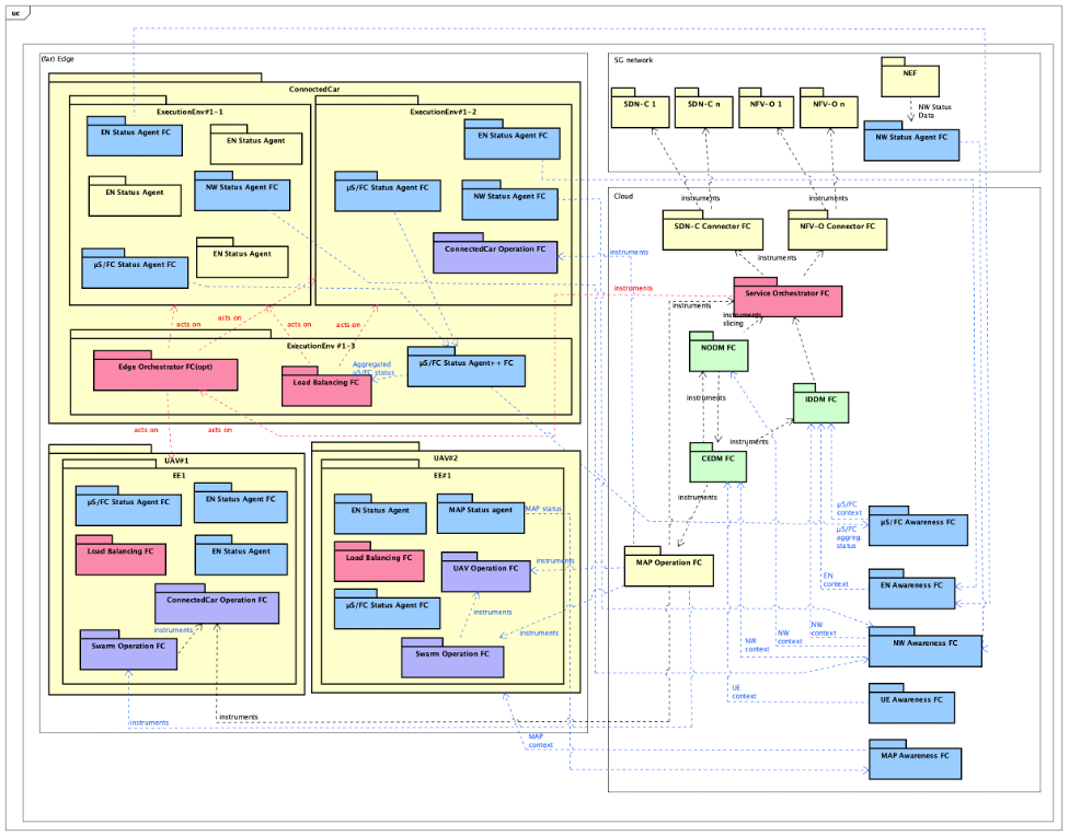
Figure 3: MAP Operation and its specialized far edge-deployed operation components
IDaaS and CEaaS
We now start the second part of this post with the introduction of the Coverage Extension as a Service and Intelligence Distribution as a Service (CEaaS and IDaaS respectively).
Those two services are related to the two top Actors and arrows which are shown at the very left of Figure 2.
We have introduced those two concepts when we found out that CE and ID should be more than 5G system operation-focused, and ought to be two services that a Vertical could seek as a support to running their own business in a better way, especially when they need for a determined amount of time, coverage extension and cloud computing-like support.
As we will see below, a Vertical can come with its own set of services (called micro-services or µS) and eventually edge nodes. It would then entrust the DEDICAT 6G platform via IDaaS to execute/manage them in an optimal and automatized way. Additionally, it could also expect a specific area to be covered (just imagine the organization of a rave party in a near-white area) using CEaaS.
So, the starting point of any scenario involving Verticals consists of a Vertical requesting CE or ID support to DEDICAT 6G, which is done via a web-based dashboard. We summarize below what kind of information the Vertical provides the platform with, at the time of the request as far as CEaaS and IDaaS are concerned:
- CEaaS:
- Start date/time and end date/time of the service
- Needed capacity (number of UEs to serve)
- Expected minimum bandwidth
- Expected maximum latency
- Location and area to be covered
- IDaaS information
- A set of vertical-owned MAPs and their description (possibly empty)
- IDaaS:
- A set of µSs, including their execution and networking constraints
- A set of vertical-owned Edge Nodes (possibly empty) and an associated deployment policy. If the list of EN is empty, DEDICAT 6G will deploy the µSs (if any) either at the DEDICAT 6G cloud side (or at the MAPs side if extended coverage is also requested)
In DEDICAT 6G, CEaaS always includes a IDaaS part (though that part may be empty) and both are done at once. As soon as such a request is analysed by DEDICAT 6G and approved, a whole new phase of actions is initiated by the platform.
Part 3 – Coverage Extension as a Service and Intelligence Distribution as a Service
Open for business with Verticals – CEaaS and IDaaS
We concluded the previous post with two lists of information passed on to the dashboard by the Vertical at the time of a CEaaS (resp. IDaaS) request.
This information is vital for the platform (CEDM and IDDM) to be able to come up with proper sets of parameters that satisfy the QoS and general service constraints stated by the Vertical.
In a nutshell the final CEaaS/IDaaS service configuration must ensure that:
- there are enough edge nodes for the optimal execution of all µSs, FCs and NFs needed (including those provided by the vertical, if any);
- the networking aspects are dimensioned properly;
- the chosen set of MAPs for coverage extension (including MAPs provided by the vertical, if any) satisfy the networking constraints and requested QoS;
So, the preliminary negotiation phase occurring between the vertical and the platform is crucial because at the end of the process, all parameters are embedded into an SLA which acts as a technical contract between the Vertical and the Platform. This SLA will be enforced by the platform during the whole service delivery period.
During this decision process, the platform must decide if it can fulfil the Vertical requests, based on its parameters. To do so, the IDDM and CEDM must perform a deep analysis before either accepting the request as such (meaning based on the request parameters only) or coming up with a counter proposal which includes the provision of additional DEDICAT 6G-owned MAPs and Edge Nodes.
This process is illustrated -using the UML use-case notation- in Figure 1 for the CEaaS case (which includes more parameters than the IDaaS one). This protocol, as used here, is the simplest case of the more general Contract Net protocol where normally a consumer agent requests resources from a set of competing provider agents (we have only one provider in our case which is the platform).
This figure is taken from a real project Use Case scenario: UC2 “Enhanced Experience”. We can see – following the usual registration/authentication steps in the two first bubbles- the Request CE action, where the request parameters (very much simplified in this figure) are passed on to the CEDM via the Dashboard. We also can notice that the CEDM relies on the IDDM to check the feasibility of the ID part of the request, while the CEDM focuses on its own CE-related check. The figure also shows different possible outcome which are OK, or Counter Proposal or NOK.
Then the Vertical is given the options of acknowledging the OK replied by the CEDM, or accepting/denying its counter proposal. The next bubbles of that figure show what comes next when the deal is concluded. All EN and µS descriptions, deployment policies, µS images are uploaded to their respective platform registries and repositories. Figure 2 provides an additional level of detail using sequence diagrams.
The possible negotiation outcomes are shown in three rectangles at the bottom of the figure.
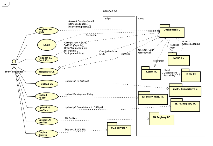
Figure 4: CEaaS request related processes
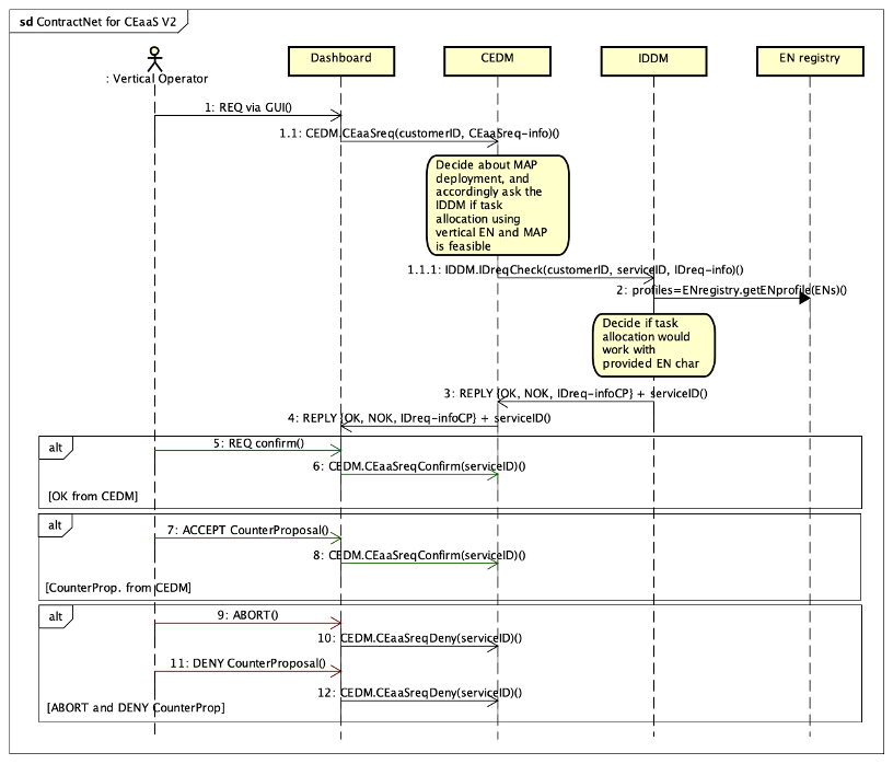
Figure 5: Contract Net sequence diagram
IDaaS and CEaaS set-up
After the end of the negotiation phase, a lot remains to be performed by several components, and in a certain order. But some information relating to this service set-up is already known since they were checked during the request analysis phase by the CEDM and IDDM; i.e., the CEDM knows about MAPs (number and class) and the IDDM knows about Edge Nodes (number and class) and Vertical µSs (their characteristics/constraints and number of instances). Keeping this in mind, the following steps are:
- The IDDM needs to deploy all FCs that are needed for basic ID and CE operation. This deployment is dictated by the “D6G” deployment policy. Following those rules, Status Agents, Load Balancing and Edge orchestrator are deployed to ENs side, some CE related components such as UAV Operation and Swarm Operation are deployed at the MAPs side; Those deployments are rather static and do not go through any optimization process. This process occurs during the next step. All FC instances are created in the µS/FC Registry;
- Since we have now deployed all supporting mandatory components, the IDDM can compute the optimal placement of all Vertical µSs, following the rules of the Vertical deployment policy. Such rules might provide full deployment flexibility (any EN/MAP) or on the contrary might restrict µS deployment to a designated EN (typically a Vertical-owned EN which has been tailored to the µS in term of memory, CPU/GPU usage etc.). At the end of this second step, the IDDM duties are fully completed;
- In this third step, the CEDM entrusts
- the MAP Operation to implement its CE decision (as performed already during negotiation phase) which includes MAP additional configuration (NF-focused) and;
- the NODM to create a dedicated Network Slice.
The following Figure 6 shows the steps described above in a message sequence chart.
In this figure:
- arrows 1 and 2 are about concluding the CEaaS request and storing the SLA in its registry respectively;
- arrows 3 to 13 are the steps discussed with the UML use-case figure where information is uploaded to their respective registries and repositories;
- arrows 15 to 28 are dealing with standard MAP-specific FC deployment by the IDDM;
- arrows 29 to 39 are dealing with standard FC deployment at EN side;
- arrows 40 to 51 are dealing with µS placement;
- arrows 52 & 53 relate respectively to points a) and b) above.
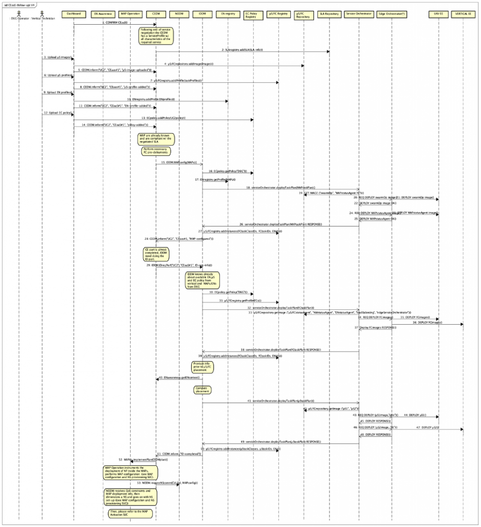
Figure 6: CEaaS from the IDDM and CEDM perspectives
The two steps a) and b) involving respectively the MAP Operation and NODM FCs are elucidated and illustrated in the next part.
Part 4 – Coverage Extension as a Service continued
MAP configuration and deployment
As we already discussed in earlier parts, the MAP Operation FC is responsible for implementing the part of the CEDM FC decision that relates to MAP configuration, MAP operation and also the execution of the CE service as a whole (meaning its entire life cycle). To be more precise, the tasks that the Map Configuration FC is responsible for includes:
- deploying communication related network functions such as IAB-MT, donor-DU into each MAP;
- configuring the MAPs according to the CE-service specifics such as start and stop time/day;
- configuring the MAP according to networking specifics;
- instrumenting the physical deployment of the MAPs to their pre-determined location (involves a human operator and the Dashboard FC);
- managing the MAPs life cycle (activating /starting/stopping/deactivating) MAPs;
- managing the CE service life cycle (start/stop);
- informing the CEDM about the service delivery progress and eventually receiving from the CEDM updated service characteristics (via an updated decision).
During that process, the MAP Operation FC shall receive a network slice provisioning notification from the NODM FC. Since this is a mandatory step prior to the CE service actual start, the MAP Operation FC will stay on-hold until such a notification is eventually received. The process leading to the emission of this notification is the purpose of the next section.
Coming back to the MAP Operation FC and its role in supplying the CE service to the Vertical, we now provide a sequence diagram (see Figure 1 below) that summarises the steps elucidated above. In this figure:
- arrow 1 shows the initial request from the CEDM FC, where a CEDM plan is passed on to the MAP Operation FC;
- arrows 2 to 4: concern the MAP configuration (communication part);
- steps 2&3 in the list above are direct calls to MAP methods and are not shown in the sequence diagram;
- arrows 5 to 9 relate to the physical deployment of the MAPs
- arrows 10 shows (at an arbitrary place in the diagram) the NS provisioning notification sent by the NODM FC
After this last step, the MAP Operation can initiate the CE service delivery at the date and time specified within the service profile.
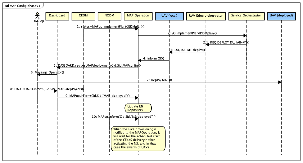
Figure 7: MAP configuration
Network slice setup
At the same time the MAP Operation receives a message from the CEDM FC focussing on MAPs and service specifics, the NODM FC receives a message from the CEDM FC that relates to the characteristics of a Vertical-tailored network slice which is meant to implement the QoS requirements agreed between the Vertical and the CEDM FC at the time of the CEaaS negotiation. In order to implement the CEDM decision, the NODM FC must then interact with the 5G system in order to provision that slice.
As we could see, the general characteristics of the NS are decided by the CEDM FC but its technical dimensioning and ultimately its provisioning are part of the NODM FC duties.
To do so the NODM FC interacts with the 5G system relying on the Service Orchestrator FC, and the NFV-O & SDN-C connectors at the DEDICAT 6G side and their counter parts at the 5G side as shown in the Figure 8 below.
The NS dimensioning decision carried on by the NODM FC is embodied within two templates: the NST (Network Slice Template) and NSST (network Slice Subnet Template) which are passed on to the Service Orchestrator for implementation at the 5G side (via the DEDICAT 6G NFV-O and SDN-C Connectors and their 5G/MANO NFV-O & SDN-C counterparts).
It is worth mentioning that the service logics that determines the content of the NST and NSST templates is not described or specified in the architecture document, however the related interfaces between the NODM and the Service Orchestrator on one side and between the Service Orchestrator and both the NFV-O and SDN-C on the other side, are indeed elucidated.
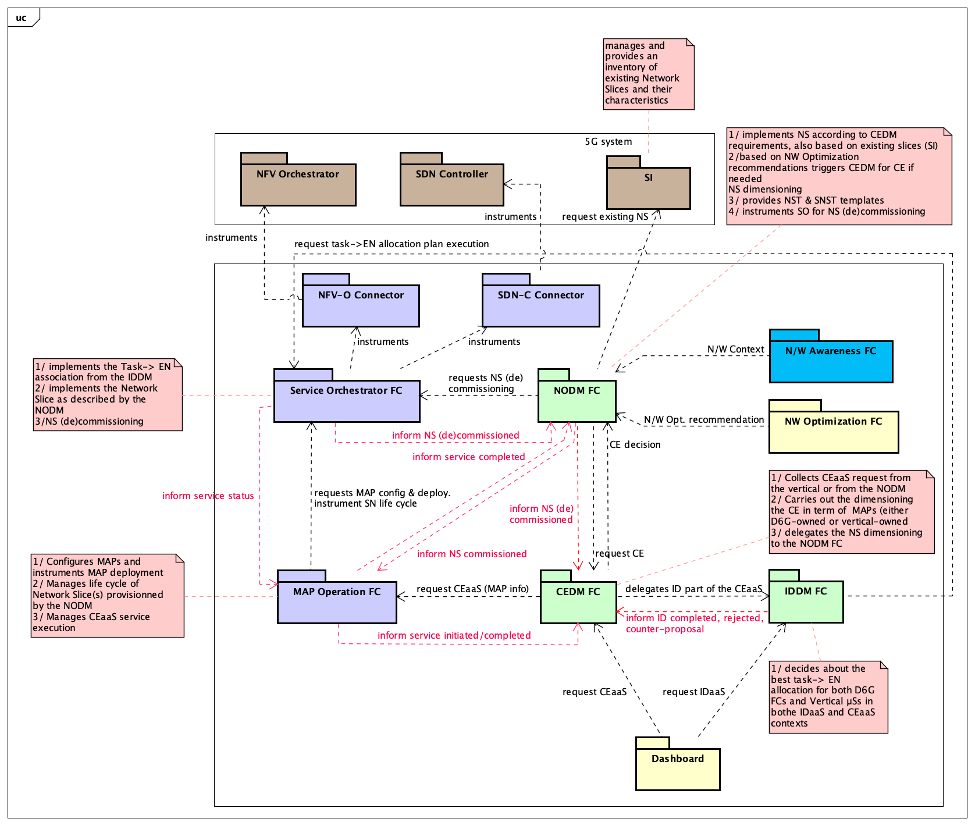
Figure 8: Decision-making FCs and their interactions
The figure above focusses only on interactions between the three major decision-making components and on the interactions between those three components and their supporting FCs.
Signalling messages are shown in red. Additional essential interactions taking place between the MAP Operation and the set of MAPs it manages are not shown in this figure. In order to provide a complete view of the CEaaS set-up, we complete our description with the sequence diagram that relates to Network Slicing (see Figure 9 below).
In this figure:
- Arrow 1 shows the initial request from the NODM FC to the Service Orchestrator FC, asking for the implementation of the NST;
- Arrows 2 to 4 show the request from the Service Orchestrator FC to the SDN-C Connector FC where the networking part of the slice is set-up;
- Arrows 5 to 7 show the request from the Service Orchestrator FC to the NFV-O Connector FC where the deployment of virtualized network functions is dealt with;
- Arrows 8 to 10 are about signalling. In particular, the NODM FC informs the MAP Operation FC that the network slice has been commissioned.
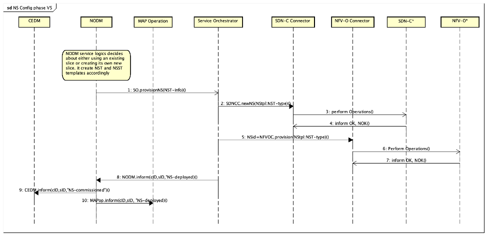
Figure 9: Network Slice commissioning
After those two essentials steps, namely MAPs configuration & deployment and network slice set-up haven been completed, the MAP Operation is then in charge of starting the CE delivery to the Vertical at the agreed date and time.
Part 5 – The Integrated Access and Backhaul (IAB) concept
With this fifth and final blog entry, we delve into the Integrated Access and Backhaul (IAB) concept and how it is used in DEDICAT 6G in order to extend existing 5G Radio Access Network (RAN) coverage. Then, we elucidate an example of coverage extension using combined solution based on both CEaaS and IAB, in the context of Disaster Relief.
Integrated Access and Backhaul
IAB was introduced initially in Rel.16 of 3GPP[1]. Its main role is to provide an alternative to optical backhauling by enabling so-called IAB node to serve UEs (or another IAB node) while providing a (usually mmWave based high bandwidth) backhaul link toward a gNB. In short, IAB provides NG-RAN with wireless relaying capabilities.
We will see in the second section dedicated to Disaster Relief, how this technology proves to be extremely suited to the densification of radio coverage over complex geographic configuration like collapsed cities, rugged terrain and known/accidental “white” areas.
From the 5G RAN architecture point of view, a gNB is made of several components: the Radio Unit (RU) which is mostly electronics/radio front-end, and two software components which are the Distributed Unit (DU) and Central Unit (CU). The DU is meant to be distributed, hence located in the physical proximity of a gNB while the CU can be optionally centralised, e.g., virtualised in the 5G cloud.
It is then possible to deploy several IAB-nodes that act as a chain of relays until the special gNB -called IAB-Donor- is reached towards the 5G core network side. The IAB-donor and each of the IAB-nodes can serve both UEs and/or other IAB-nodes, forming a chain of nodes providing (potentially) routing over multiple hops between UEs and the IAB-donor, by means of a Backhaul Adaptation Protocol (BAP).
Figure 10 below shows the 5G standalone architecture (Core + RAN) and the part of DEDICAT 6G which interacts with it. For that later part, strong similarities can be found when comparing that top/left part of the figure below with the upper part of Figure 2 in the second part.
Focussing on the RAN bottom part of Figure 10, we can see that each IAB-node embeds two components 1/ the IAB-DU (which plays the same role as the donor-DU in the IAB-Donor) and 2/ the IAB-MT (for Mobile Termination). The IAB-donor, in addition to the classical CU, also embeds the IAB-donor-DU.
The general rule of thumb is that an IAB-DU in a parent IAB-node is connected to the IAB Mobile Termination (IAB-MT) in the child IAB-node. Each IAB-DU can also serve directly UEs, even if serving also at the same time one or several neighbour IAB-nodes. However, depending on the configuration and location, a UE could experience multi-hops connection to the terminating serving gNB.
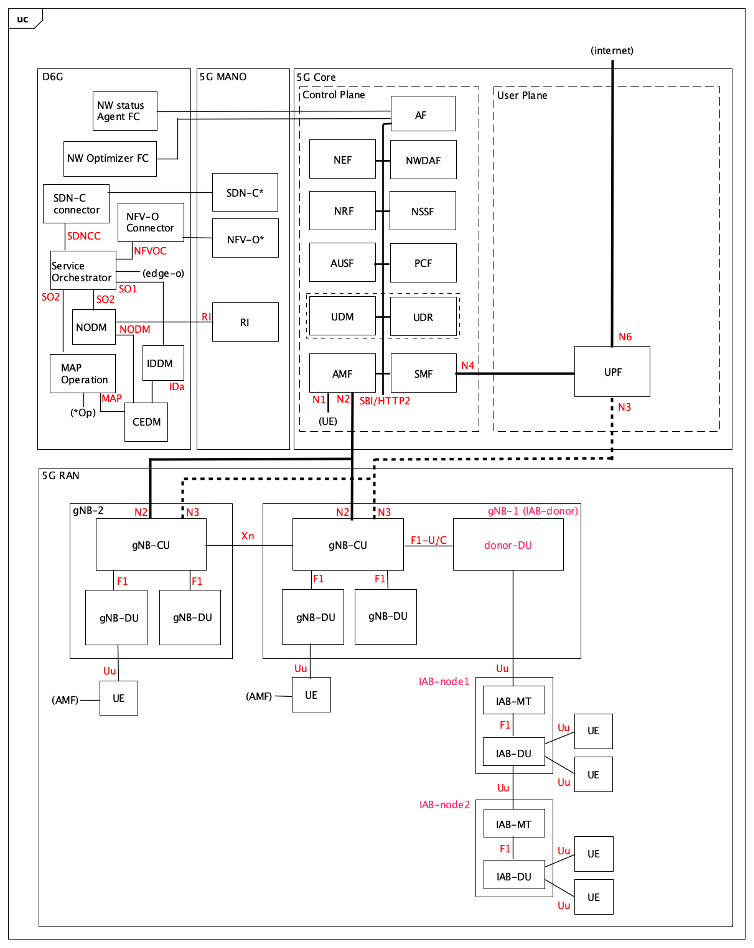
Figure 10: simple relay configuration with 1 IAB-donor + 2 IAB-nodes
In the next section we show how we can take advantage of the IAB technology and CEaaS (as introduced in earlier posts), in order to build up complex -but still flexible- coverage extensions.
Using IAB and CEaaS for Disaster Relief
If we do a quick review of recent earthquakes, we find that they often occur in rural areas where terrain characteristics make the work of rescue teams particularly difficult. It becomes even more critical when cities collapse, creating pockets of “white” areas where communication does not go through, either due to equipment failure or shadowing effect resulting from the disaster.
In addition, as a matter of fact, such disasters happen most often in developing/emerging countries where existing communication infrastructure is more vulnerable and often does not provide full territory coverage, especially in rural or mountain areas.
When rescue teams are deployed on site, they may rely either on existing local mobile network (if any is still standing) or on deploying their own communication tactical bubble if such local cellular communication networking is not existing or no more available.
A third additional option involves the use of IAB technology and CEaaS principles. To support that case, we assume that 1/ there is still at least one operating gNBs nearby the disaster site (even if they don’t provide it with radio coverage) 2/ the rescue team is equipped with IAB-enabled access points such as drones, crawling robots, man packs etc. and 3/ DEDICAT 6G platform can interact and cooperate with the local 5G network.
The following Figure 11 shows an example of MAP deployment which can be used to bring 5G communication from the last (distant) standing gNB all the way to the deployed rescue team.
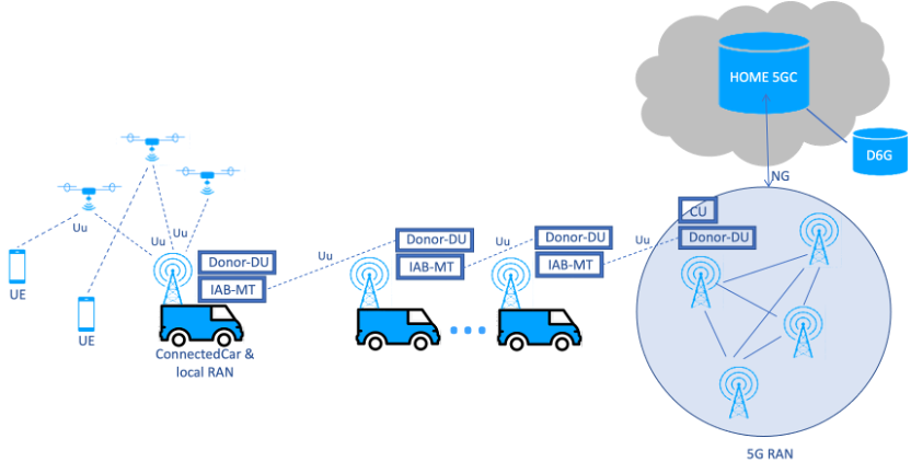
Figure 11: MAP deployment scenario involving connected cars (relay & on-site) and drones
We can see in this figure above, that DEDICAT 6G platform and Home 5G network team up in order to extend coverage towards the disaster zone. This coverage extension is using relays at first in order to reach the rescue team ConnectedCar, which then is used as a “hub” to densify even further the coverage inside “white” pockets. This figure shows 3 drones, but any configuration is indeed possible and a wide range of MAPs with different characteristics can be used for different purposes. For instance, crawling robots can be used to provide video feeds from inside collapsed buildings or independent smaller rescue teams can be deployed with man packs whenever the disaster area is particularly large.
IAB -combined with CEaaS- offers a lot of flexibility and any situation can easily come with its own optimized MAP deployment.
Coming back to CEaaS, the subscription request to this service comes with all data concerning 1/ the MAPs (their type, number per types, and capability descriptions as explained in earlier posts) 2/ micro-services to be deployed with the MAPs (such as MCS software suite), 3/ QoS requirements etc… Next a dedicated slice is created and used for communication by the UEs via the declared MAPs part of the network slice.
The next Figure 12 shows the architecture of such a deployment. Relay IAB-nodes are in blue and the red ones are those deployed at the disaster site.
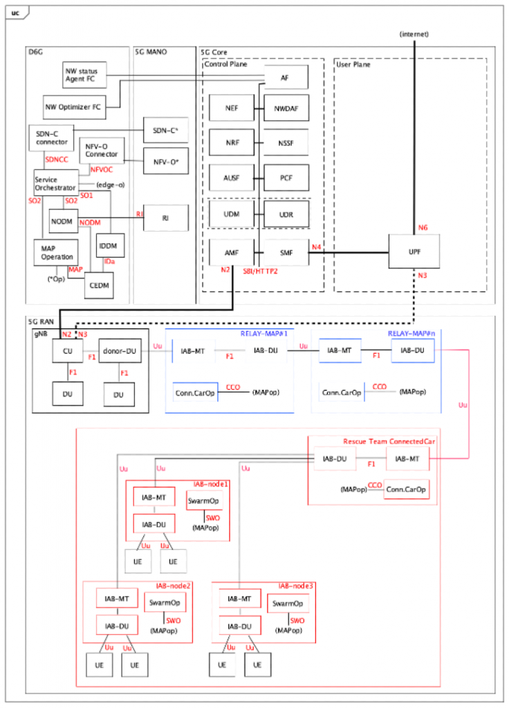
Figure 12: Architecture of Disaster Relief scenario
This fifth part concludes the introdurcion to the DEDICAT 6G system architecture. More information can be found in Deliverable D2.5 which is available here at the DEDICAT 6G web site: https://Dedicat6g.eu/results/deliverables/
Any comment or question can be addressed to Dr. François Carrez (lead architect) at the following email address: f.carrez@surrey.ac.uk
[1] https://portal.3gpp.org/desktopmodules/Specifications/SpecificationDetails.aspx?specificationId=3191 for an introduction. For more detail check also that one out: https://portal.3gpp.org/desktopmodules/Specifications/SpecificationDetails.aspx?specificationId=3219